Supporting popular measuring microscope and optical comparator systems
worldwide.
Features & Benefits
• Clean, Intuitive Design
The user interface design of the M2 software means you’ll
spend more time measuring and less time reading manuals. By
combining a familiar user experience with current touch screen
conventions, the M2 software can quickly be integrated into your
process and accessible to a wide range of users.
• Available in Horizontal or Vertical formats.
The M2 software interface is available for use in either portrait
mode or landscape mode. This option provides maximum
flexibility for your choice of display device or mounting system.
• Support for Optical Edge or Crosshair measuring systems.
Gain access to many of the same powerful features, and
intuitive measuring environment, whether using an optical edge
equipped system or an externally generated crosshair device.
Precise optical edge detection mechanisms provide accurate
results as well as access to powerful, industry first, measurement
functionality.
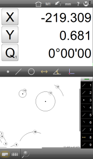
Your M2 is available in either a portrait or landscape format.


Designed for Multi-Touch software control.
In addition to the conventional mouse interface, expanded Multi-Touch logic allows for versatile pan and zoom of the active part view. Increase the efficiency of feature construction, feature data
manipulation, and reporting tasks with a simple pinch zoom, swipe pan, or double click.
Use popular navigation moves including pinch zoom and swipe pan to increase feature construction efficiency.
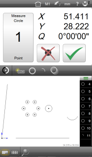
Advanced crosshair probe toolbox.
For Optical Edge enabled systems, both “simple” and “auto edge” crosshair probes are available. The “auto edge” probe captures points on edges automatically upon crossing. The M2’s EdgeLogic™ system (Optical Edge enabled systems only) enables gesture driven control of start and end measurement commands. Start and finish measurements quickly, without the need for direct software interaction.
The M2’s EdgeLogic™ system (Optical Edge enabled systems only) enables gesture driven control of start and end measurement commands.
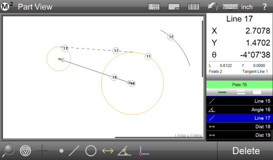
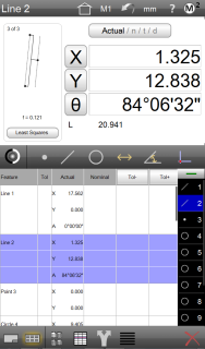
Graphics-based “Part View” constructions.
Generate popular construction types, like Distances and Tangent Lines, from within the graphical part view itself. Constructions with
multiple sub-types can be toggled quickly with the change feature type command.
Supported construction types include:
* Average * Mid/Center Point(s) * End Point(s)
* Intersections * Shortest Distance * Farthest Distance
* Tangent Line(s) * Gage Circle(s) * Bolt Circle
* Angle Compliments * Perpendicular/Parallel Line(s)
* Offset Skew Lines
Generate popular construction types including Distance and Tangent Lines from with the graphical part view.
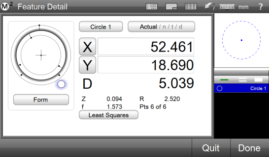
Feature Detail Graphics.
Individual feature views provide informative drawings displaying point cloud distributions, as well as nominal deviations, and tolerance results. Scroll through your measured features list from this view for a feature by feature display of Actual,
Nominal, Tolerance, and Deviation results. Set the
desired data fit type from the “Actual” screen using the “fit toggle” button.
Scroll through your measured features list from this view for a feature by feature display of Actual, Nominal, Tolerance, Deviation, and Data Fit Type information.
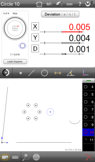
Geometric tolerancing.
You may measure features, set nominals, apply tolerances and view deviation
results with only a few quick clicks. You may also apply a variety of popular tolerance types to features in the standard “feature-to-feature” fashion, or utilize the “place tolerancing” system for applications where tolerances are specified in a block tolerance style call out. For these cases the M2 software let’s you enter and apply universal tolerance values according to your feature resolution groupings.
Supported tolerances include:
* X/Y/Z Positional
* Diameter/Radius/Length/Width Size
* Theta (Angle)
* Form
* Parallelism
* Angularity
* True Position (LMC/MMC Modifiers)
* Straightness
* Perpendicularity
* Roundness
* Concentricity
* Runout
Measure features, set nominals, apply tolerances and view deviation results quickly and easily.
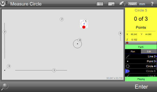
Part programs and playback.
Playback or edit groups of measured, constructed, and created features from a saved part program file. Part program files, when loaded, will prepare the M2 software to repeat
a sequence of feature measurement steps, printed reports, and exported measurement data. The playback guidance mechanism provides helpful on-screen instruction for successful
playback of your part programs.
Playback or edit groups of measured, constructed and created features from your saved part program file.
Reports.
Flexibility for report contents and formatting allows for full customization
of the data format, header information, and header and footer graphics. Part view graphics, time and date stamps, and operator information can all be included for any report type.
Reports can be viewed, printed, or exported at the conclusion of a
single inspection routine, or they can be included in a part program
to support repetitive or automated measurement and reporting.
Reports can be printed as hard copies to standard Windows compatible
printers, or exported as data files in popular file formats.
Report data formats include:
* Standard Report
* Tolerance
* CSV
* European Reports
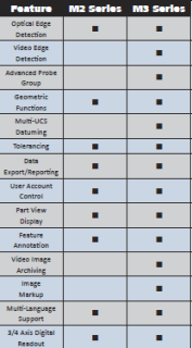
MetLogix M Series Features Matrix